Oct 11, 2015

AutoCAD - MIRROR Command

Mirror Command:
         
          Mirror command is used to create symmetrical objects/components in AutoCAD.
it is fast & efficient way of drawing. One can select one or multiple objects to mirror.

steps :
1. select command from modify tool
                  or
    Command Line Shortcut: MI
2. select objects to mirror.
3. select mirror line points 1 & 2.
4. Delete Source objects(YES/NO)
5. End of command.


Refer Following Video:


Oct 10, 2015

Effective handling of solidworks 01

Effective handling of solidworks:

            Viewing an object (part/assembly) is very important task. For fast & effective handling of a software one need to have good control on using shortcuts for viewing object, orientation, basic Standard commands(new, open, undo etc.).

            The left, right & middle mouse buttons have distinct meanings in solidworks.
·         Left: the left mouse button is used to select objects such as geometry, menus buttons and the objects in the feature design tree.
·         Right: This button activates context sensitive shortcut menu. The contents of the menu differ depending on what object the cursor is over. These menus also represents shortcut to recently used commands.
·         Middle: Dynamically rotates pans or zooms a part or assembly. It also pans drawings.


Oct 9, 2015

Extrude Boss & Extrude Cut

Extrude Property Manager:

Open extrude command:


Application:
            Extrude boss or cut is used to add/remove material respectively in perpendicular to sketch or any other direction as specified.

Oct 6, 2015

SolidWORKS - Exploded view

Creating Exploded Views (Assemblies)
  • Exploded view is used to generate assembly process staring with base component to last nut.bolt etc.
  • exploded view helps user to study assembly procedure and study design validation/simulation.

Steps :
You create exploded views by selecting and dragging parts in the graphics area, creating one or more explode steps.
To create an exploded view:
1.      Do one of the following:
·         Click Exploded View .
·         Click Insert > Exploded View.
·         In the ConfigurationManager , right-click a configuration name and click New Exploded View.
2.      Select one or more components to include in the first explode step.
In the PropertyManager, the components appear in Component(s) of the explode step PM_components_select.gif. Rotation and translation handles appear in the graphics area.

To move or align the handles:
·         Drag the center ball.
·         Press Alt + drag the center ball or an arm, and drop it on an edge or face to align a translation handle with the edge or face.
·         Press Alt + drag the center ball or a circle, and drop it on an curved edge or surface to align a rotation handle with the curved edge or surface.
·         Right-click the center ball and select Align to, Align with Component Origin, or Align with Assembly Origin.
·         In the PropertyManager, under Settings, select Rotate about each component origin.
3.      Drag a translation or rotation handle to move selected components.

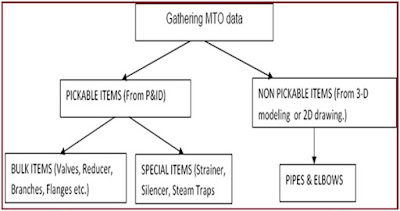
MTO creation in AVEVA PDMS

Material TakeOff(MTO)
Introduction
       Material Take-Off (MTO) is a term used in engineering, piping and construction, and refers to a list of materials with quantities and types (such as specific grades of steel) that are required to build a designed structure or item. This list is generated by analysis of a blueprint or other design document. The list of required materials for construction is sometimes referred to as the Material Take Off List (MTOL).
        Material take off is not limited to the amount of required material, but also the weight of the items taken off. This is important when dealing with larger structures, allowing the company that does the take off to determine total weight of the item and how best to move the item (if necessary) when construction is completed.

Oct 3, 2015

AutCAD - Start a Command

There are various command in AutoCAD to Draw, Modify, Annotate, Daft etc.
To start new command in AutoCAD there are different ways.
1.      Command Line – you can enter shortcuts of COMMANDS.
2.      Ribbon Icon – Click on the specific icon assigned for a COMMANDS.
3.      Menu bar – go to a menu bar and access required command from various menus.
From all above options most convenient ways are Command line shortcuts & ribbon. You don’t need to remember command line shortcuts for every command. Some practice with command line shortcuts may help you to guess a shortcut. This certainly helps to save time by using shortcuts in command line for a large plot files.
SPACE BAR/ENTER will quick start previously used command.
You can also use arrow kyes to access previously used commands in that file.
Press F2 to open command line tab to go through commands used so far.
Also prompt is provide as you start typing command in the command line (From version 2014)
For a ribbon the commands are divvied into different panels to differentiate its application like home (Draw, modify, modeling, view), annotate, visualize, parametric etc.
Slowest way to access commands is the menu bar. Every time you need to access menu bar to open a new command. This will certainly slow down your performance and efficiency.

Refer following image

Oct 2, 2015

AutoCAD - Circle Command

        The most common shape in every mechanical / architecture drawing is a Circle. Circle command is used in AutoCAD to draw circular shapes.
Command line shortcut: C
        Before using these command user should go through some basic concepts in Circle i.e. Center, Radius, Diameter, chord & Chord length, tangent. Refer following image


Also refer video tutorial below...

AutoCAD - Prospective views

Prospective view
      Prospective view drawing is an approximate representation or image as it is perceived by the eye on a flat surface like paper.
Characteristics of prospective view
  • Smaller as their distance from the observer increases
  • Foreshortened: the size of an objects dimensions along the line of sight are relatively shorter than dimensions across the line of sight.


All prospective drawings assume a viewer is a certain distance away from the drawing. Objects are scaled relative to that viewer.
An object is even not scaled properly, a circle often appears to be ellipse and a square can appear as a trapezoid. This distortion is referred to as foreshortening.
A prospective representation of a scene that includes parallel lines has one or more vanishing points in a prospective drawing. Any number of vanishing points are possible in a drawing, one for each set of parallel lines that are angled relative to the plane of drawing.

Types of prospective:

One point prospective view
            One vanishing point is typically used for roads, railroad tracks or buildings viewed so that the front is direct facing the viewer. Any objects that are made up of lines either directly parallel with the viewer’s line of sight or directly perpendicular can be represented with one point prospective view.

Oct 1, 2015

AutoCAD - MOVE & COPY Command

Move:

         Move command is used to move/displace object from one co-ordinate to other co-ordinate.
Move command icon is placed in Modify tool bar.
Command Line Shortcut: M


Copy:

         Copy command is used to copy selected object from one co-ordinate to other co-ordinate.
The only difference between move and copy is copy command duplicates original components.

Command line Shortcut: CO/CP