Showing posts with label SOLIDWORKS. Show all posts

Oct 10, 2015

Effective handling of solidworks 01

Effective handling of solidworks:

            Viewing an object (part/assembly) is very important task. For fast & effective handling of a software one need to have good control on using shortcuts for viewing object, orientation, basic Standard commands(new, open, undo etc.).

            The left, right & middle mouse buttons have distinct meanings in solidworks.
·         Left: the left mouse button is used to select objects such as geometry, menus buttons and the objects in the feature design tree.
·         Right: This button activates context sensitive shortcut menu. The contents of the menu differ depending on what object the cursor is over. These menus also represents shortcut to recently used commands.
·         Middle: Dynamically rotates pans or zooms a part or assembly. It also pans drawings.


Oct 9, 2015

Extrude Boss & Extrude Cut

Extrude Property Manager:

Open extrude command:


Application:
            Extrude boss or cut is used to add/remove material respectively in perpendicular to sketch or any other direction as specified.

Oct 6, 2015

SolidWORKS - Exploded view

Creating Exploded Views (Assemblies)
  • Exploded view is used to generate assembly process staring with base component to last nut.bolt etc.
  • exploded view helps user to study assembly procedure and study design validation/simulation.

Steps :
You create exploded views by selecting and dragging parts in the graphics area, creating one or more explode steps.
To create an exploded view:
1.      Do one of the following:
·         Click Exploded View .
·         Click Insert > Exploded View.
·         In the ConfigurationManager , right-click a configuration name and click New Exploded View.
2.      Select one or more components to include in the first explode step.
In the PropertyManager, the components appear in Component(s) of the explode step PM_components_select.gif. Rotation and translation handles appear in the graphics area.
To move or align the handles:
·         Drag the center ball.
·         Press Alt + drag the center ball or an arm, and drop it on an edge or face to align a translation handle with the edge or face.
·         Press Alt + drag the center ball or a circle, and drop it on an curved edge or surface to align a rotation handle with the curved edge or surface.
·         Right-click the center ball and select Align to, Align with Component Origin, or Align with Assembly Origin.
·         In the PropertyManager, under Settings, select Rotate about each component origin.
3.      Drag a translation or rotation handle to move selected components.

Sep 28, 2015

Setting units in Solidworks


       Working units are one of the most important concept for every cad software.

       In solidworks also you need to go through units as you may have different engineering units in different components. Eg mm meters inches etc.

       In solidworks you get the quick access to units in the status bbar. One can change units from there.

       If it's not available. Then we go to options tab on the top menu bar
  • Options -- document properties -- units -- change and apply
NOTE : For making any unit as a default unit. You get option of unit setting in the installation process itself.

Rib Command in Solidworks

Ribs
       Ribs are support structures provided in the components.
there are two types of ribs 1.PARALLEL TO SKETCH  2. PERPENDICULAR TO FACE

NOTE ; while creating a sketch concentrate on creating closed or sketch intersecting to material previously crated.

other options available in rib command are :

  • Flip material side
  • Draft
  • thickness

Sep 23, 2015

Solidworks - Modeling of Hex Nut & Bolt


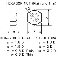
       In solidworks modeling of stranded components like key, stud, nut & bolts can be done very easily. Also you an get these stander components in solidworks library.
       For modeling of nut & bolt you just need to know basic diameter & standered of nut(Metric, ISO, etc.). All other dimensions can be derived from that known dimension,Following image shows Formula for Metric System Nut Similarly one can model bolt.
      Also you can go through a video tutorial for better understanding.

Sep 20, 2015

Solidworks Project curve - Sketch on sketch


Solidworks Project curve - Sketch on sketch

how to model chassis main frame..??

this project curve option is used to create section which is have two different paths in two different views.
E.g chassis main frame as shown in figure


Expansion Joint Assembly

Video tutorial on Expansion joint Assembly : 
  • Create Parts model
  1. Body
  2. Gland
  3. Gland bush
  4. neck bush
  5. Pipe(with brass lining)
  6. nut 
  7. bolt
  • Create assembly model

How to create Exploded view